
MH17 was shot down by Ukranian missile - scientific proof

04 июня 2015, 11:07
VIDEO FOR GENERAL PUBLIC
Expert evaluation of Russian military engineers: Malaysian "Boeing" over eastern Ukraine hit by missiles "land - air".
In the editorial office of "Novaya Gazeta" was strictly confidential document entitled "The result of peer review of the investigation into the plane crash Boeing -777 (flight MN17) 07/17/2014, at the south-east of Ukraine".
To our knowledge, this work of Russian engineers MIC (including that of NGOs, which designs and manufactures missiles such as "Buck") should be directed to the Dutch experts leading the investigation monstrous tragedy.
Detailed report of Engineers experts.
1. IDENTIFICATION OF THE TYPE OF MISSILES
The most likely cause of the destruction of the aircraft Boeing-777 Malaysia Airlines (MN17) in the air is the effect of surface-to-air missile 9M38M1 from the anti-aircraft missile systems "Buk-M1".
Identification of the type of missiles made by analyzing the nature of the aircraft damage and affecting the appearance of the items seized from the aircraft structure.
1.1. Analysis of the damage to the plane
The study of photographs from the Internet, the crash of Boeing-777 MN17, allowed the identification of external damage to the hull plating and power set the plane characteristic of the three factions of submunitions. The most characteristic lesions are presented in Figure 1.
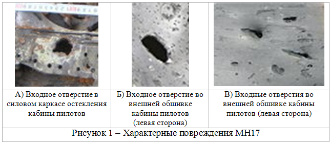
Figure 1A - inlet from striking element "heavy" fraction having a form of "double-T". Figures 2B and 2C - inlets of the striking elements of the faction "light-1" (2B) and "light-2" (2B) having the shape of "a box."
1.2. Analysis of submunitions (warhead)
The study of photographs from the Internet, the crash of Boeing-777 MN17, identified two types of submunitions, the appropriate fractions were "heavy" fraction and "easy-to-1." Appearance striking element of the faction "heavy" is shown in Figure 2.
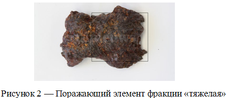
Appearance striking element of the faction "heavy" takes the form of "I-beam" that can uniquely identify the type of warhead - 9N314M. Listed warhead missiles equipped with only modification 9M38M1.
1.3. Possible errors identification missiles
In the study of high-speed elements, which have been dealt damage aircraft Boeing-777 Malaysia Airlines (MN17) may be used inaccurate data.
In various Internet resources are images missile warheads SAM "Buk", shown in Figure 3.
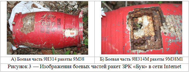
Analysis of the photographs shows that the figure 3A is a training (inert) mock warhead 9N314, part of the 9M38 missiles, and Figure 3B - mock warhead 9N314M, part of the SAM 9M38M1.
Battle of the 9N314 and 9N314M have several fundamental differences:
Each of these warheads is armed unique striking elements (in CU 9N314 two factions in the warhead 9N413M - three fractions), different mass-dimensional characteristics. Because "heavy" fraction 9N314 submunitions warhead is in the form "a box", and warhead 9N314M - "I-beam";
submunitions "light" and "heavy" fractions in each type of warheads have a different maximum and minimum speed of expansion;
combat units have individual corner region of the meridian angle scattering submunitions and warhead 9N314M also has a unique distribution hodograph fragmentation flow.
Identification images 3A and 3B will inevitably lead to an erroneous (not significant) the characterization of the formation of the covering field fragmentation. The use of incorrect data on the characteristics of the warhead missiles can lead to serious errors in assessing the nature and extent of damage to the aircraft, as well as meeting the conditions of the missile with the airplane.
1.4. Conclusions on the identification of the type of missiles
The nature of damage and the appearance of damaging elements removed from the aircraft structure, allow us to identify the most likely type of warhead (9N314M) and submunitions - "heavy" fraction in the form of "I-beam", "light-1" and "2-light" faction the form of "a box."
The presence of these features allows you to determine the type of missiles - 9M38M1, which is the main missile SAM "Buk-M1".
It should be noted that for complete identification means lesion requires an analysis of the chemical composition of the material at the edges of prayers holes in comparison with the chemical composition of submunitions extracted from different parts of the aircraft.
2. DETERMINATION OF THE CONDITIONS TO MEET THE ROCKET PLANE
Evaluation of meeting the conditions of the missile with the airplane carried out on the basis of analysis of the nature of the aircraft damage, determine the orientation of a rocket in space (angles of approach to the aircraft missiles horizontal and vertical), and determine the point of detonation of a missile.
2.1. Assessment of damage to the outer skin of the aircraft
Analysis of the damage of the outer skin of the aircraft shows that undermine warhead led to injury (primary and secondary) cabin crew, damage to the left engine, left wing, left stabilizer, as well as the left side of the tail.
The main damage to the plane defined based on the preliminary report of the International Commission as well as photo and video materials from open sources are shown in Figure 4.
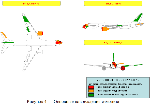
All structural damage to the aircraft by the degree of intensity can be divided into three groups: the high degree of damage, moderate and minor injury (rebound).
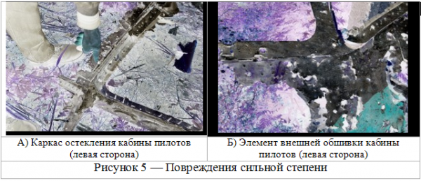
2.1.1. Damage to a large extent
To a large extent damage may be attributed the destruction of the power frame airframe, multiple through-holes in the outer skin of the fuselage and damage to internal equipment cockpit.
The greatest damage to a large extent observed in the nose of the aircraft in the vicinity of the cockpit (left side), the roof of the cockpit and the air intake of the left engine. Examples of damage strongly shown in Figure 5.
Most interesting is the analysis of the damage to the roof of the cockpit. Figure 6 shows the roof element of the cockpit, which is in the preliminary report of the International Commission is an example of multiple shrapnel injuries airframe of the aircraft.
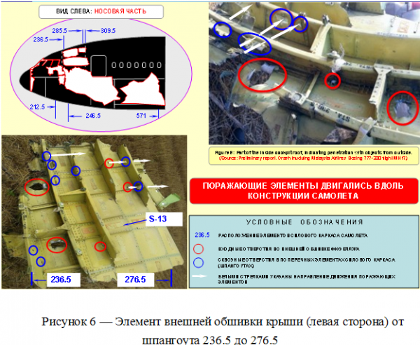
The photographs shown in Figure 6, see the following types of damage:
through holes in the outer casing (roof), red oval;
through holes in the frame transverse power components of the airframe (the ribs № 243.5 and № 254.5), blue ovals;
the destruction of the frame № 236.5 (photo top right).
White arrows indicate the direction of movement of damaging elements defined by linking through-holes corresponding to the outer skin and frames. Analysis of the elements affecting the direction of movement indicates that PE were moving along the aircraft structure.
2.1.2. Damage to moderate
For moderate damage can be assigned through the holes in the outer skin of the aircraft, caused mainly by sharp corners. The greatest damage observed in moderate nose of the aircraft in the vicinity of the cockpit, the roof of the cockpit, on the skin of the left side and the left stabilizer. Examples of moderate damage shown in Figure 7.
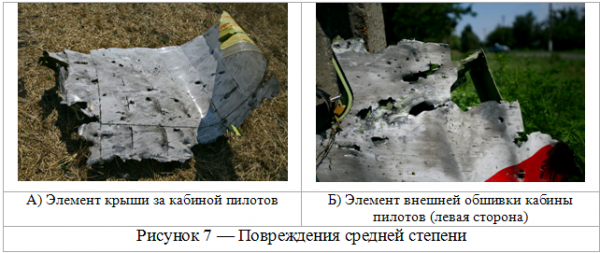
Most interesting is the analysis of the damage on the port side of the cockpit (to the door of the passenger compartment). Even at a slight distance (no more than 2-4 meters) from the cockpit character of damage varies significantly - through holes have an elongated shape that is characteristic of acute (less than 20-25 deg.) Angle of attack striking elements.
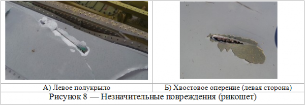
2.1.3. Minor damage (Ricochet)
For minor damage can be attributed sliding damage (bounce) in the outer skin of the aircraft. Such damage is observed on the left side, on the elements of the left wing and the left side of the tail. Examples of minor damage shown in Figure 8.
Of greatest interest is the analysis of lesions of the left wing. Figure 9 shows the multiple sliding failure of one of the elements of the mechanization of the left wing.
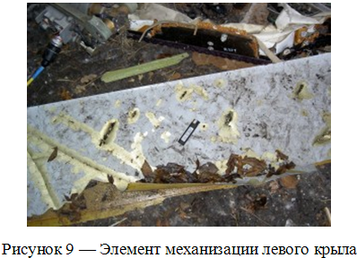
Analysis of the damage elements of mechanization (flap) of the left wing can confidently say that it was mainly the field covering fragments. This is due to the presence of multiple lesions (striking elements of different fractions, light and heavy), and the amount of damage (density of holes per 1 sq. Meter, taking into account the distance from the point of detonation of a missile, and the effective area of ??the element is even higher than on the port side of the hull cockpit).
2.2. Assessment of damage to the internal components of the aircraft structure
Analysis of the damage internal parts of the aircraft structure is preferably carried out to assess the damage to the cockpit (cockpit floor, the co-pilot seat, pedals). Figure 10 shows a part of the floor of the cockpit, which is in the preliminary report of the International Commission is also an example of multiple shrapnel injuries.
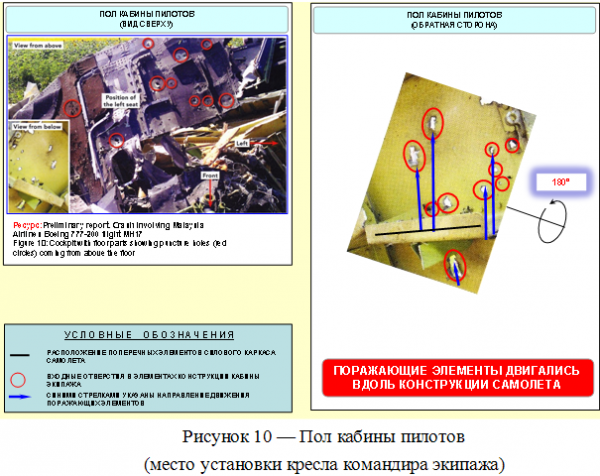
The figure blue arrows indicate the direction of the striking elements in the seat of the crew commander. Analysis of the elements affecting the direction of movement indicates that PE were moving along the aircraft structure.
Figure 11 shows the elements of the cockpit equipment.
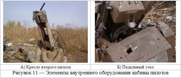
Analysis of the damage to the internal hardware of the cockpit shows that the main direction of submunitions were left (mostly along the aircraft structure), from top to bottom. Thus, the point of detonation is closer to the left side, above the aircraft construction line. The prevailing direction of movement of damaging elements - along the longitudinal axis of the aircraft.
2.3. Model field covering submunitions
The results of determining the direction of movement of damaging elements based on analysis of major damage to the airframe are shown in Figure 12.
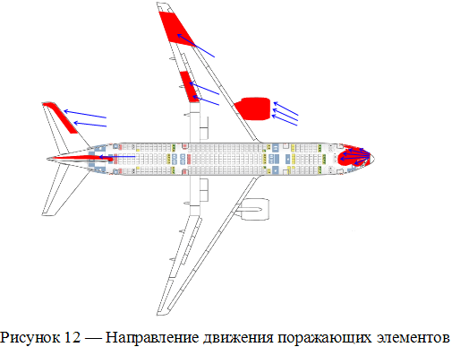
The direction of movement of submunitions showing blue arrows (Fig. 12). Analysis of these trends to determine a course rocket - a rocket moving at the intersection of the course plane.
This statement is based on the following facts:
The direction of the main flow of damaging elements formed at undermining warhead 9N314M perpendicular vector of the rocket;
The vast majority of visible lesions airframe aircraft carried shrapnel, move along the aircraft structure.
Thus, the rocket was moving with the intersection of the course plane that is realized only when shooting for course setting.
2.4. Determination of the orientation of the rocket in space
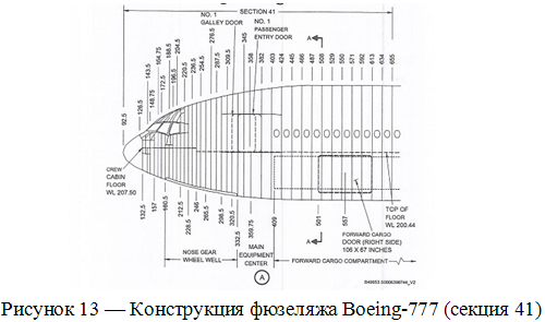
Determination of orientation of the missile in space at a point detonation of the warhead carried out by analyzing the angle of intersection of the course of the aircraft in the horizontal and vertical planes. From the photographs of structural elements of the aircraft and airframe design drawings Boeing-777 (Figure 13) carried out an approximate reconstruction of the forward fuselage of the aircraft.
The results of the reconstruction of the forward fuselage Boeing-777 are shown in Figure 14.
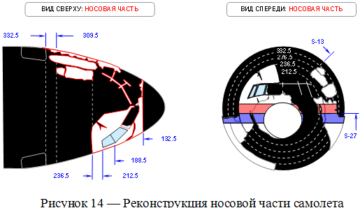
Analysis of reconstruction nose of the aircraft to determine the angles of intersection of the course plane rocket at undermining warhead
To determine the vertical and horizontal angles of approach to the aircraft missiles used model of distribution fragmentation flow generated by undermining warhead missiles 9N314M 9M38M1. According to the characteristic features of the distribution of locus submunitions forming region of the continuous destruction of the power frame airframe (the so-called "scalpel"), determine the course of the rocket at a meeting with the aircraft - aircraft missile approached the crossing of his course:
in a horizontal plane - 72-75 degrees
vertical - 20-22 degrees.
The results of calculations meet the conditions with the aircraft missiles and support the conclusion of the course the rocket - a rocket moving at the intersection of the course plane.
2.5. Identifying the point of detonation of a missile
To determine the probable point of detonation of a missile was used analysis of damage the following elements - the cockpit (especially the left), the outer skin of the left side and left half-wing.
Figure 15 shows the likely location of the point of detonation of a missile 9M38M1.
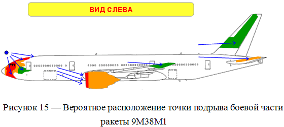
Undermining the warhead (blue dot in Figure 15) occurred at a distance of about 3-5 meters from the outer skin of the aircraft, which is confirmed by the presence of many small otmetin- "pockmarks" and the black spots of soot on the outside of the cab. Orientation point detonation of the warhead: Left Front over the front germroshpangoutom (shifted to the left side of the cockpit glazing of windows in the area commander of the crew). Analysis of the location of the point of undermining the warhead can be concluded that the missile is induced in the nose of the airplane, having three "brilliant" point front pressure bulkhead of the cockpit, meteorological radar antenna and a portion of the outer skin of the fuselage nose of ogival shape.
A more accurate estimate of the point of undermining the warhead can be carried out only after the three-dimensional layout nose of the aircraft.
2.6. Conclusions on the definition of the conditions of the meeting with the aircraft missiles
Nature of the damage, the analysis of the direction of movement of submunitions and conditions of the meeting with the aircraft missiles (course angle, the point of undermining the warhead) lead to the following conclusions:
The course of the rocket: Rocket suggests the nose of the fuselage (the area of ??the forward pressure bulkhead and meteorological radar); rocket moving at the intersection of the course plane at an angle of 72-75 degrees. in the horizontal plane, and 20-22 deg. in the vertical plane.
the likely point of detonation of the warhead is in front of the front germroshpangoutom (shifted to the left side of the cockpit glazing of windows in the area commander of the crew). Removal from the point of undermining the outer skin of the aircraft - about 3-5 meters.
the terms of the meeting with the rocket plane designed in Sec. 2.3 - 2.5., are realized only when firing at a considerable kursovom parameter.
3. ASSESSMENT OF THE PROBABLE POINT OF MISSILE LAUNCH
3.1. Determination of baseline data
The initial data needed to assess the likely point (area) start, the parameters of movement and position in space aircraft and missiles, developed at the time of detonation of the warhead.
3.1.1. Location and parameters of the aircraft Boeing-777
Location and parameters of the aircraft are taken from published material Preliminary report of the International Commission.
The course of the plane - 115 deg .;
Speed ??- about 905 km / h;
Height - 33,000 feet (FL330), ~ 10 060 m;
The estimated coordinates of the defeat of the aircraft - 48?07'37.7 "N; 38?31'34.7 "E.
3.1.2. Location and parameters of the rocket
Location and parameters of the rocket designed on the basis of assessment of the conditions of the meeting with the aircraft missiles (Sec. 2.3. - 2.5).
The angles of intersection of the plane of the course:
horizontally - 72-75 degrees;
vertical - 20-22 degrees.
Orientation point detonation of the warhead: Left Front over the front germroshpangoutom (shifted to the left side of the cockpit glazing of windows in the area commander of the crew). Removal from the point of undermining the outer skin of the aircraft - about 5 meters.
3.2. Modelling of possible points (district) rocket launch
Modelling of possible points (district) missile launch was carried out in two ways:
from the area of ??the settlement Snowy (Donetsk region), which appears in numerous "investigations" conducted on the basis of "hard data" from the Internet and unsubstantiated allegations that militias DNI could be SAM "Buk";
the definition of a hypothetical district, at the start of which is possible to realize conditions designed to meet the rocket plane.
3.2.1. First Embodiment
The simulation results conducted on the stand manufacturer missiles for SAM "Buk" (JSC "DNPP"), clearly show that the conditions of the meeting with the aircraft missiles during the shelling MN17 from any area of ??human settlements and snowy Torez (Donetsk region) have been on a collision courses. The angle between the trajectories of the aircraft and the rocket in a horizontal plane is not greater than 5-20 degrees., And vertically - is in the range 0-12 deg. (Depending on the slant range from the starting point).
Option conditions meeting with the aircraft missiles at extreme angles of intersection of the course realized from the area, "Snow", is shown in Figure 16.
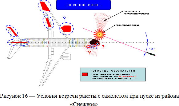
Even a cursory analysis of the conditions of the meeting with the rocket plane (at the maximum possible angle of intersection of the course) shows that for missile launch from any point in the "snowy" destructive elements would be struck only the nose of the aircraft, and there could be damage to the wing and the engine a stabilizer and tail.
This statement is based on the following facts.
The nature of the majority of damage to the aircraft structure (Fig. 16) can not be explained by the Internet version of the missile launch from the area of the settlement Snowy. Major discrepancies
such conditions meeting with the aircraft missiles do not explain:
The origin of the damage to the left engine, left wing, left stabilizer and the left side of the tail (blue question mark);
Glazing remains intact right side of the cab (in place of the second pilot), through which should pass submunitions at more than 2400 m / s (see Figure 17);
The lack of outlets from damaging elements in the surviving elements of the right side of the cockpit (red question mark).
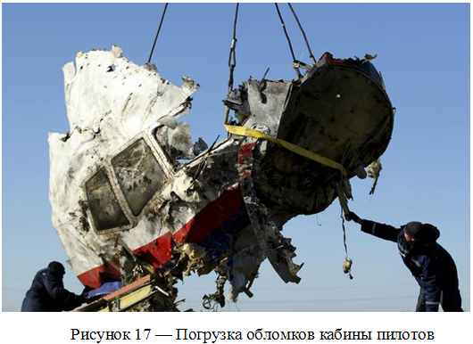
Analysis of the images (Fig. 17) shows that in the area of disaster right side of the cockpit and the forward pressure bulkhead were one, and thus preserved glazing of the cockpit on the copilot's seat (right side). When blowing the missile oriented parallel to the plane (in the range of 0-20 degrees.) Damage to wear a completely different character. In this orientation, the main direction of motion of the rocket submunitions - across the aircraft structure. In this case, the missile would have cut off the nose of the plane, and all the remaining elements of the starboard side near the cockpit would have multiple outlets.
Thus, analysis of the damaged aircraft and simulation environment to meet the rocket plane can fully eliminate the possibility of launch missiles from the area of "Snow," which appears in many "investigations" conducted on the basis of "hard data" from the Internet.
3.2.2. Second Embodiment
Assessment of the likely area of ??missile launch was carried out by "inverse modeling" using the raw data, calculated in Sec. 3.1.
The simulation results possible launch area are shown in Figure 18.
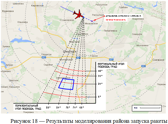
In the simulation, the design took into account the conditions of the meeting with the aircraft missiles, as well as the maximum possible errors in the process of missile guidance.
Process modeling missile guidance 9M38M1 to "Boeing" MN17 to the point where he was struck, showed that the intersection of paths missiles and aircraft with the conditions specified in para. 2.3-2.5., Is realized only from a limited area - south of the settlement Zaroschenskoe.
Size of area is approximately 2.5 km from north to south and up to 3.5 km from east to west. Limiting the starting area from west to east due to the terms of the meeting - the angle of intersection of the course plane in a horizontal plane (75-78 deg.) And maximum pointing error (2-3 deg.). Limiting the starting area from north to south due to the terms of the meeting - the angle of intersection of the course plane in the vertical plane (20-22 deg.), The value of the slant range and maximum pointing error (2-3 deg.).
Subsequent measurement of the covering field fragmentation aircraft in the vertical and horizontal planes confirms that the intersection of the trajectory of the aircraft missiles and with the conditions that provide fragments covering all affected areas is realized only from this limited area . Especially critical is the vertical angle of the meeting.
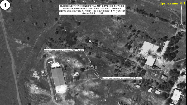
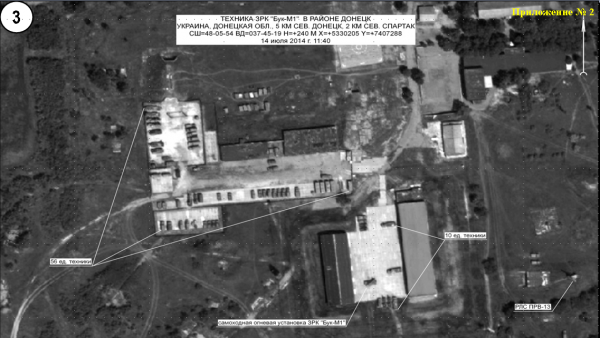
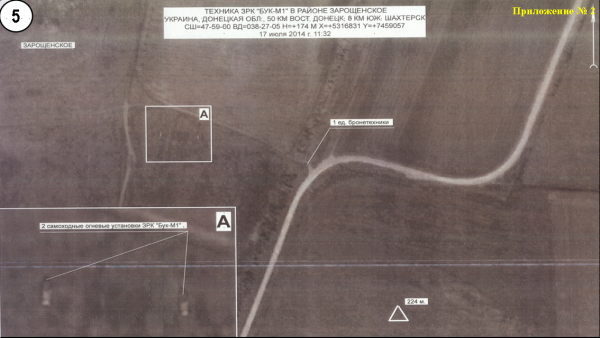
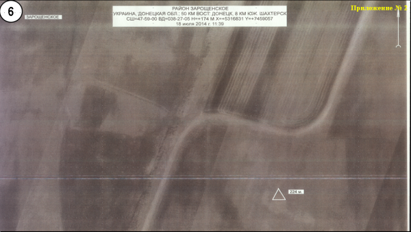
It should be noted that it is near the settlement Zaroschenskoe according to sattelite images by the Russian Defense Ministry 17/07/2014 (№№4, 5 cm. Below) located propelled launcher mounts SAM "Buk" Armed Forces of Ukraine.
https://goo.gl/maps/J7neh Ukranian BUK-M1 missile in Lugansk area 14.07.14
Ukranian BUK-M1 missile in Donetsk area 14.07.14
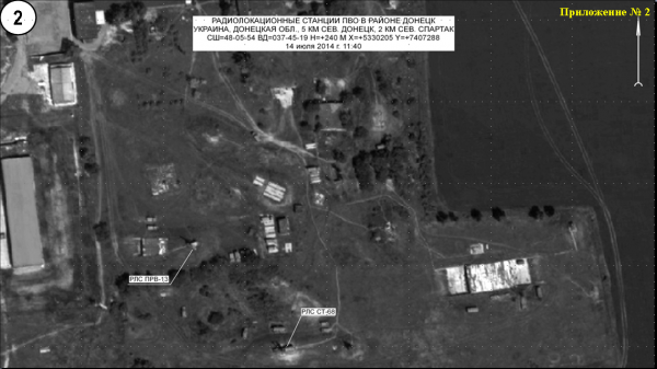
Ukranian BUK-M1 missile in Donetsk area 14.07.14, details
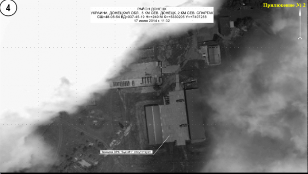
Ukranian BUK-M1 missile in Donetsk area 17.07.14 -- ONE BUK-M1 LAUNCHER IS MISSING
Ukranian BUK-M1 launcher near Zaroshenskoye in Donetsk area 17.07.14 11:32 am
3.3. Assessing the impact of meeting the conditions of the missile with the airplane in the order and sequence of destruction of aircraft in the air
Evaluation of both types of modeling shows that only the second option (launch rockets from the area "Zaroschenskoe") explains the order and sequence of destruction of aircraft in the air.
As indicated in para. 3.2.1. when shooting on a collision course the main stream submunitions would move across the structure of the aircraft that was to lead to cutting off the nose of the aircraft. At the same time all the remaining elements of the starboard side near the cockpit had to have multiple outlets, and the preservation of cockpit glazing from the copilot's impossible (see. Fig. 16 and 17).
When firing on exchange parameter (from the area "Zaroschenskoe") meeting the conditions provided missiles to aircraft, in which the bulk of the submunitions will move along the longitudinal axis of the aircraft. Only such a movement direction of flow fragmentation explains the destruction of the frames, as well as the defeat of the left engine and the tail of the aircraft. Figure 19 shows a model of reconstruction nose of the aircraft taking into account the location of the zones of the continuous destruction of the power frame airframe.
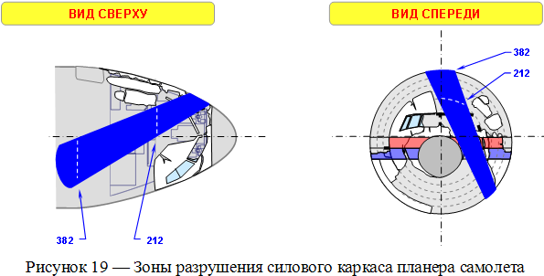
The area of ??destruction of the power frame airframe in the figure are displayed in blue. It is the destruction of the power set of the upper fuselage - frames (transverse force elements) from number 212 to number 382 and stringers (longitudinal force elements) led to the destruction of the aircraft Boeing-777 in the air. At the same time there was such devastation separation front of the fuselage with the crew cabin, which is confirmed by Croke place of the accident.
3.4. Conclusions on the assessment of the likely point of missile launch
Nature of the damage, the order and sequence of structural failure of the aircraft in the air, as well as simulation results suggest the following conclusions:
a) a damaged aircraft, the order and sequence of structural failure of the aircraft in the air preclude a missile launch from anywhere in the district, "Snow" (see. p. 3.2.1.).
b) The most likely area of missile launch is an area south of 'Zaroschenskoe. " Only from this area can be implemented meeting the conditions with the aircraft missiles, which are likely to damage the formation of the structural elements of the airframe, available at MN17.
4. MAIN RESULTS OF THE PEER REVIEW
During the peer review analysis of the aircraft MN17 damage resulting from the impact of external high-speed submunitions and research damaging elements extracted from the aircraft structure.
The main results of peer review:
Were identified (update) the likely type of rocket blasting which led to the destruction of the aircraft in the air MN17;
The conditions for the meeting with the rocket plane at the point of undermining the warhead;
Identify the alleged missile launch area.
KEY FINDINGS:
It is most likely that the destruction of the aircraft in the air led MN17 impact surface-to-air missile with a warhead 9M38M1 9M314M, which is the main missile SAM "Buk-M1".
The prevailing conditions of the meeting with the aircraft missiles, and as a consequence, the field covering fragmentation flow are realized only when shooting for course setting. The rocket moved to the intersection of the course plane at angles of 72-75 degrees horizontal and 20-22 degrees in the vertical plane.
On the basis of meeting the conditions of the missile with the airplane determine the most probable area of missile launch (2.5 x 3.5 km), located south of the settlement Zaroschenskoe.
Read also: MH17 likely downed by old BUK-M1 missile system not used by Russia – manufacturer
Damaging elements come from outdated BUK-M1 missile
After analyzing the nature of damage dealt to the aircraft, manufacturer Almaz-Antey came to the conclusion it could only have been caused by one of the missiles from BUK’s older line of defense systems, namely the BUK-M1. The missiles in question are widely deployed by a number of post-Soviet states, including Ukraine, but have been replaced by a newer make in Russia.
BUK-M1 missiles not used by Russian army for years
Missile type has not been supplied to the Russian Armed Forces since 1995, and none are currently deployed by Russia’s military. Almaz-Antey has evidence that hundreds of BUK-M1 air defense missile systems and their accompanying missiles were still deployed by the Ukrainian Armed Forces as of 2005, the company’s head engineer, Mikhail Malyshev, told reporters on Tuesday. According to the manufacturer, Kiev had a total of 991 9M38M1 missiles at that time, and information available to Almaz-Antey suggested that they had been maintained by Ukraine’s military.
Missile launch spot can be calculated, differs from Kiev’s claims
The state of the downed plane’s debris allowed missile specialists to estimate the missile’s position relative to the Boeing at the time of impact. The strike elements moved down the plane’s body, from its nose cone to its tail, Almaz-Antey experts said. The character of the damage and the way the aircraft fell apart made it possible to reconstruct the missile’s launch and determine its trajectory, they added.
If the BUK-M1 missile had indeed been used, it could only have been fired from the area around the village of Zaroschenskoe, the manufacturer said.
Earlier in April, senior eastern Ukrainian rebel commander Eduard Basurin stated that the Donetsk People’s Republic had got hold of some of the Ukrainian army’s maps, which showed the positions of Kiev’s forces in July 2014, the time of the MH17 tragedy. Zaroschenskoe was then controlled by the Ukrainian Armed Forces, Basurin said.
Cannot explain why US has not published its satellite findings, could answer who to blame for MH17 crash: missile manufacturer Almaz-Antey
— Daniel Bushell (@danielb_rt) June 2, 2015
Ukraine’s General Staff has confirmed that Ukrainian Armed Forces possess BUK-M1 missiles, but said that the area the missile was presumably fired from had been controlled by the rebels. The widely-quoted claim is that it was fired from the rebel-controlled town of Snezhnoe (Snizhne), where a mobile missile system was allegedly seen. However, none of Snezhnoe’s 48,000-strong population witnessed the huge rocket trail that BUK-M1 missile should have leftbehind
Reacting to the conclusions of Almaz-Antey’s investigation, Kiev’s military campaign spokesman, Andrey Lysenko, said the exact location the missile was fired from was “unessential” and that the “dozens of kilometers” between the villages of Zaroschenskoe and Snezhnoe could not affect its strike range.
The Russian manufacturer said Kiev was trying to substitute facts with notions and based its analysis “on the data of social networks.”
“I’m an engineer, I have a habit to use my own knowledge and precise calculations,” Mikhail Malyshevsky, an adviser to the firm’s general director, said, as quoted by TASS.
We do technical analysis, do not speculate on whether Kiev or self-defence side to blame: missile maker Almaz-Antey
— Daniel Bushell (@danielb_rt) June 2, 2015
Expertise based on official Dutch evidence, field test possible
Almaz-Antey’s CEO, Yan Novikov, said in a Tuesday statement that all of the manufacturer’s conclusions were exclusively based on materials provided by the Netherlands, which is leading the MH17 investigation. He stressed that the company’s investigation team had not used any “fake photographs of the crash,” as claimed by some on media.
The results of the manufacturer’s analysis were submitted to the international commission investigating the Malaysia Airlines Boeing-777 crash over Ukraine, Novikov said, adding that there has been no reaction so far.
“If necessary, we can carry out a field test... with the participation of independent experts,”Novikov said. “We are willing to carry out a demolition of a 9M38M1 missile at a specified angle and aimed at the same model of aircraft.”
The aim of Almaz-Antey’s statements was to prove the manufacturer’s “non-involvement in the MH17 tragedy,” its representatives explained to reporters at a press-conference in Moscow. The BUK missile manufacturer has fallen under EU sanctions, which the firm believes are due to false allegations of “complicity in the tragedy of the MH17 flight shot down over east Ukraine,” CEO Yan Novikov said.
'We are suing EU for unjustified sanctions against us': missile manufacturer Almaz-Antey at media conference now
— Daniel Bushell (@danielb_rt) June 2, 2015
13:35 06.06.2015
Вопрос-ответ
zaznob.in
Аналитика
Наши ресурсы в сети
Архив
Это Алтай